Robot cart


Few days ago I’ve bought 2WD Smart Robot Car Kit For ESP8266 ESP-12E D1 Wifi Board For Arduino Control by Mobile Ultrasonic Module .

Here is the step by step assembly. Setting up the developement environment and deploying will be subject of another posts.

Start by installing the raisers for the microcontroller and the motor control board
Install both motors (just one shown) by holding it between two brackets
The back wheel
The back wheel. Do not add the board bold, they will come after the installation of battery case
The battery case
The battery case, bolted in the raisers of the back wheel.
The servo for ultrasound mount
The ultrasound mount servo top view
The servo for ultrasound mount
The ultrasound mount servo bottom view
The ultrasound mount
The ultrasound mount view from behind
The ultrasound mount
The ultrasound mount front view
Motor control board
Motors control board
Motor control board power output wiring bottom view
Motors control board power output bottom view

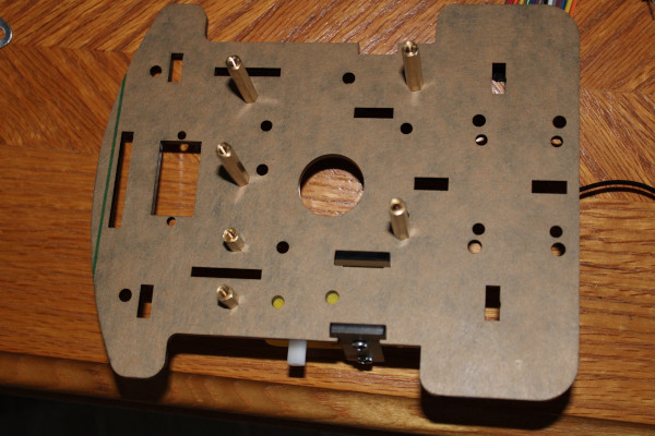
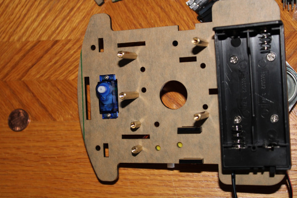
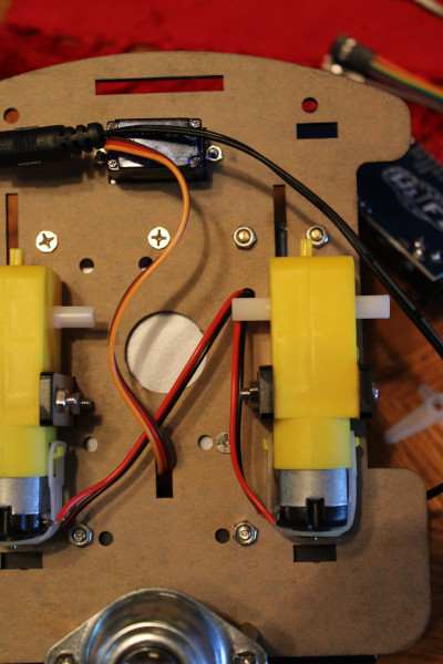
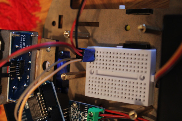
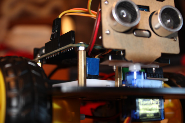
Note: do not use the large round hole, but the narrow rectangular hole near the bottom wheel. The breadboard will need to be installed above it.

Motor control board power output wiring
Motors control board power output wiring

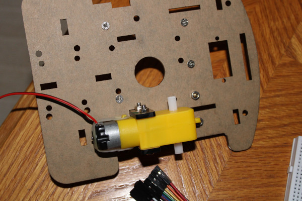
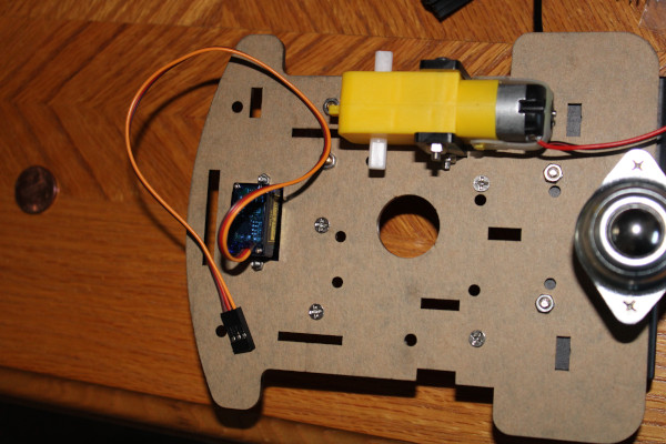
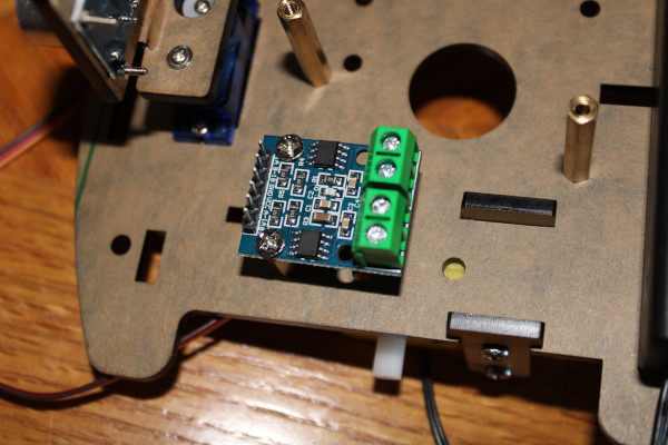
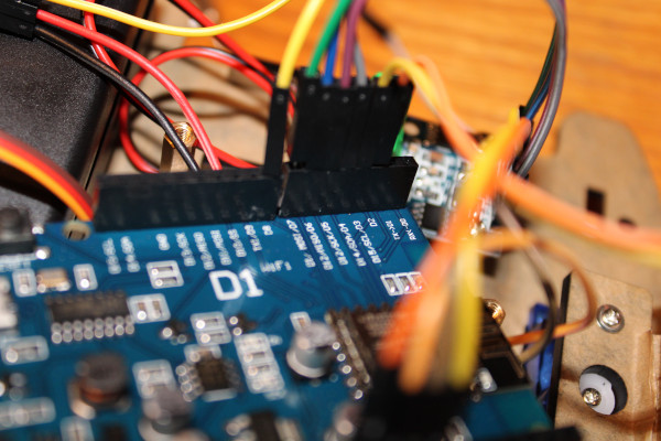
Polarity of the wires is essential. Otherwise it will either not work or it will reverse the direction of the affected motor.

Power supply of the ultrasound sensor
Output power supply for the breadboard
Breadboard power wires.

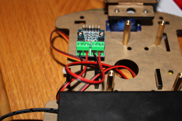
I’ve taped together all adjacent connectors, will have to worry less about one connector leaving its place.

Power wires layout
Power wires layout.
Connecting the motor control
Connecting the motor control.
Connecting the motor control
Connecting the motor control.
Connecting the motor control
Connecting the motor control.

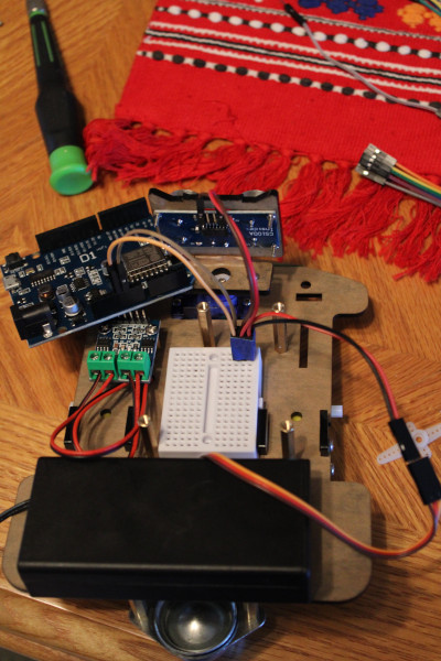
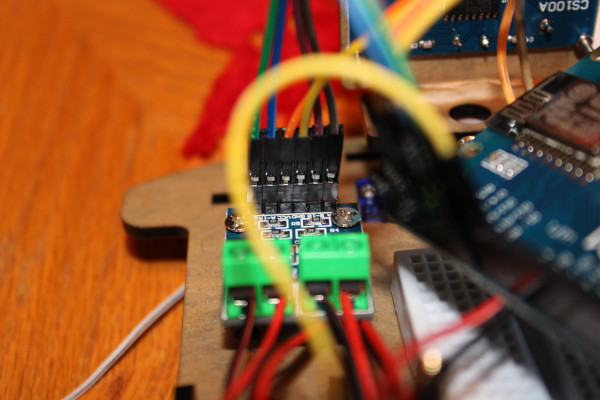
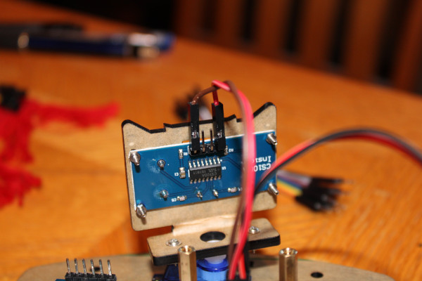
Disregard my layout of colors. I’ve figured out I’ve connected a few of them wrong; you can debug upon deploying the software to the board. Only meed to make sure the power cables are right, I won’t risk applying power to the wrong terminals or causing a shortcircuit of the battery.

Added an additional nut as an additional raiser for the Arduino board, so that the power cables are not compressed against it

Once you are done with wiring, the vehicle is ready for the software upload.

No batteries are required for testing. Make sure that the vehicle is immobilized, the wheels don’t touch the table.

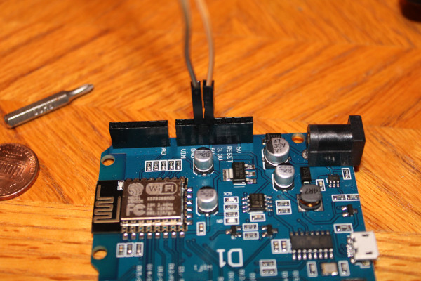
To start testing, connect the micro USB 2 cable (included) to the Arduino card and your PC.